
WELCOME TO NAN JING JSC TRADING CO., LTD.
- All
- Product Name
- Product Keyword
- Product Model
- Product Summary
- Product Description
- Multi Field Search
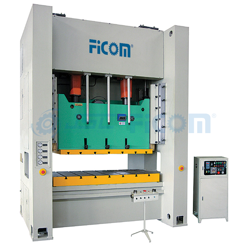 |


JM36/JMD36
FICOM
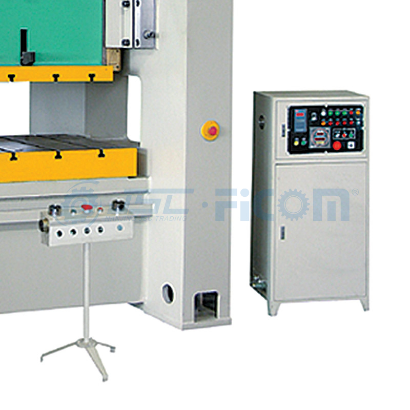
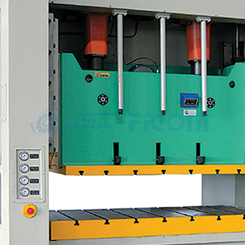
· Eight-side lengthened guide with high precision.
· Electric shut height adjustment with digital display.
· Equipped with lifting balance cylinder.
· Duplex valves imported from Japan.
· Electric compelling grease lubrication system.
· Controlled by PLC of international brand.
· Buttons, indicators, AC contactors, air circuit breakers and other controlling devices are used international brand.
· Electronic cam device with intelligent top dead center stop function and several safety function.
· Optional air cushion device, NC feeding machine, light curtain and inverter of international brand to fulfill stroke adjustment.
· JMD36 series equipped with multi pitmen framework, suitable for flat stretching.

JM36-250
| Model No. | Unit | JM36-110 JMD36-110 | JM36-160 JMD36-160 | JM36-200 JMD36-200 | JM36-250 JMD36-250 | JM36-315 JMD36-315 | JM36-400 | JM36-500 | |
| nominal force | Kn | 1100 | 1600 | 2000 | 2500 | 3150 | 4000 | 5000 | |
| stroke under nominal force | mm | 5 | 6 | 7 | 8 | 8 | 10 | 10 | |
| slide block stroke | mm | 180 | 200 | 250 | 280 | 280 | 280 | 280 | |
| number of stroke | fixed | min-1 | 50 | 45 | 35 | 30 | 25 | 20 | 18 |
| variable(optional) | min-1 | 35-65 | 30-55 | 25-45 | 20-35 | 20-30 | 18-25 | 15-20 | |
| max die set height | mm | 400 | 450 | 500 | 550 | 600 | 650 | 700 | |
| die set height adjustment | mm | 90 | 100 | 110 | 120 | 120 | 120 | 120 | |
| worktable dimensions(F.B×L.R) | mm | 680×1650 | 760×1850 | 840×2200 | 920×2300 | 1000×2400 | 1100×2500 | 1200×2900 | |
| thickness of bolster | mm | 130 | 150 | 170 | 180 | 190 | 200 | 210 | |
| dimensions of slide block bottom surface(F.B×L.R) | mm | 580×1360 | 660×1580 | 740×1850 | 820×2000 | 900×2100 | 1000×2200 | 1100×2600 | |
| size of the handle hole(diameter×depth) | mm | 3-φ60×70 | 3-φ60×75 | 3-φ60×90 | 3-φ60×90 | 3-φ70×95 | 3-φ70×95 | 3-φ80×100 | |
| distance between columns and body | mm | 1750 | 1970 | 2300 | 2500 | 2600 | 2700 | 3100 | |
| dimension of side hole(F.B×H)(calculation from surface of worktable) | mm | 650×350 | 700×380 | 800×420 | 860×470 | 900×500 | 1020×550 | 1040×600 | |
| distance between upper surface of bolster and ground | mm | 950 | 970 | 1000 | 1100 | 1120 | 1120 | 1150 | |
| main motor power | Kw | 15 | 18.5 | 22 | 30 | 37 | 45 | 55 | |
cushion (optional) | number | 2 | 2 | 2 | 2 | 2 | 2 | 2 | |
| knock out force | Kn | 55 | 80 | 100 | 125 | 125 | 125 | 125 | |
| knock out stroke | mm | 70 | 80 | 90 | 100 | 100 | 100 | 100 | |
| knock out area | mm | 370×520 | 420×620 | 470×720 | 520×820 | 520×820 | 520×820 | 520×820 | |
| outline dimension(F.B×L.R×H) | mm | 2250×2370 ×3500 | 2480×2590 ×3610 | 2680×3120 ×3930 | 2880×3370 ×4280 | 3220×3520 ×4580 | 3310×3640 ×4580 | 3880×4080 ×4750 | |
| G.W. | Kg | 21000 | 26000 | 33000 | 42000 | 49000 | 55000 | 68000 | |
· Eight-side lengthened guide with high precision.
· Electric shut height adjustment with digital display.
· Equipped with lifting balance cylinder.
· Duplex valves imported from Japan.
· Electric compelling grease lubrication system.
· Controlled by PLC of international brand.
· Buttons, indicators, AC contactors, air circuit breakers and other controlling devices are used international brand.
· Electronic cam device with intelligent top dead center stop function and several safety function.
· Optional air cushion device, NC feeding machine, light curtain and inverter of international brand to fulfill stroke adjustment.
· JMD36 series equipped with multi pitmen framework, suitable for flat stretching.
JM36-250
| Model No. | Unit | JM36-110 JMD36-110 | JM36-160 JMD36-160 | JM36-200 JMD36-200 | JM36-250 JMD36-250 | JM36-315 JMD36-315 | JM36-400 | JM36-500 | |
| nominal force | Kn | 1100 | 1600 | 2000 | 2500 | 3150 | 4000 | 5000 | |
| stroke under nominal force | mm | 5 | 6 | 7 | 8 | 8 | 10 | 10 | |
| slide block stroke | mm | 180 | 200 | 250 | 280 | 280 | 280 | 280 | |
| number of stroke | fixed | min-1 | 50 | 45 | 35 | 30 | 25 | 20 | 18 |
| variable(optional) | min-1 | 35-65 | 30-55 | 25-45 | 20-35 | 20-30 | 18-25 | 15-20 | |
| max die set height | mm | 400 | 450 | 500 | 550 | 600 | 650 | 700 | |
| die set height adjustment | mm | 90 | 100 | 110 | 120 | 120 | 120 | 120 | |
| worktable dimensions(F.B×L.R) | mm | 680×1650 | 760×1850 | 840×2200 | 920×2300 | 1000×2400 | 1100×2500 | 1200×2900 | |
| thickness of bolster | mm | 130 | 150 | 170 | 180 | 190 | 200 | 210 | |
| dimensions of slide block bottom surface(F.B×L.R) | mm | 580×1360 | 660×1580 | 740×1850 | 820×2000 | 900×2100 | 1000×2200 | 1100×2600 | |
| size of the handle hole(diameter×depth) | mm | 3-φ60×70 | 3-φ60×75 | 3-φ60×90 | 3-φ60×90 | 3-φ70×95 | 3-φ70×95 | 3-φ80×100 | |
| distance between columns and body | mm | 1750 | 1970 | 2300 | 2500 | 2600 | 2700 | 3100 | |
| dimension of side hole(F.B×H)(calculation from surface of worktable) | mm | 650×350 | 700×380 | 800×420 | 860×470 | 900×500 | 1020×550 | 1040×600 | |
| distance between upper surface of bolster and ground | mm | 950 | 970 | 1000 | 1100 | 1120 | 1120 | 1150 | |
| main motor power | Kw | 15 | 18.5 | 22 | 30 | 37 | 45 | 55 | |
cushion (optional) | number | 2 | 2 | 2 | 2 | 2 | 2 | 2 | |
| knock out force | Kn | 55 | 80 | 100 | 125 | 125 | 125 | 125 | |
| knock out stroke | mm | 70 | 80 | 90 | 100 | 100 | 100 | 100 | |
| knock out area | mm | 370×520 | 420×620 | 470×720 | 520×820 | 520×820 | 520×820 | 520×820 | |
| outline dimension(F.B×L.R×H) | mm | 2250×2370 ×3500 | 2480×2590 ×3610 | 2680×3120 ×3930 | 2880×3370 ×4280 | 3220×3520 ×4580 | 3310×3640 ×4580 | 3880×4080 ×4750 | |
| G.W. | Kg | 21000 | 26000 | 33000 | 42000 | 49000 | 55000 | 68000 | |
